Signal Relay spark discharge and spark extinguishing measures
2022-09-15 18:38Experiments have shown that when the current disconnected by the Signal Relaycontacts is small, there will not be a large amount of gas decomposition and arcing between the Signal Relay contacts. However, if the inductance in the circuit is large (usually there is always a certain inductance in the circuit), a high overvoltage will appear on the inductance when it is disconnected, and it will be added to the Signal Relay contact gap together with the power supply voltage. If this voltage is large enough (greater than 270~300 volts), it will cause the Signal Relay contact gap just separated by a little distance to break down and discharge. Due to the small energy of the power supply, this discharge cannot develop into an arc and disappear immediately, which is called "spark discharge", as shown in Figure 2-4.

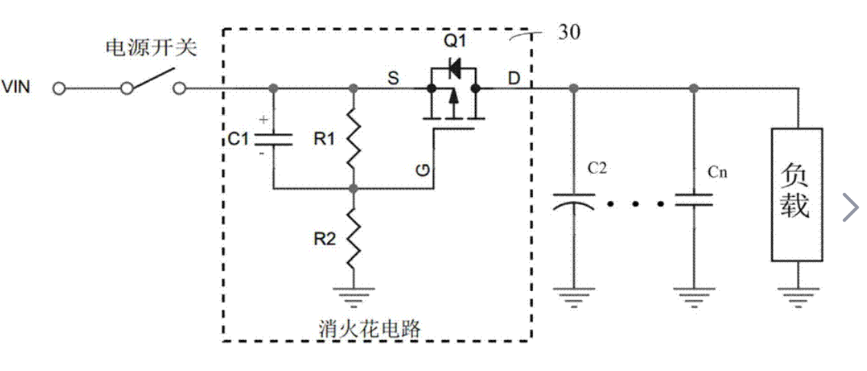
If there is a large capacitance between the Signal Relay contacts, due to the alternating current and negative conversion of the energy in the inductance and the capacitor, the spark discharge will appear and disappear, and the capacitance between the Signal Relay contacts will generate a high-frequency signal, which will seriously interfere with the surrounding radio communication. Also, spark Although the discharge is not as serious as the arc discharge, the spark discharge in Figure 24 also damages the Signal Relay contacts (mainly the cathode) and reduces the service life, so it must be eliminated. Figure 2-5 shows two spark-extinguishing circuits, the basic principle of which is to make the energy in the inductance not pass through the Signal Relay contact but pass through O (Figure 2-5a, or pass through the diode on the resistance R of the load itself when disconnected) (Fig. 2-5b) consumed. Should be When pointed out, all measures to extinguish the spark have changed the working state of the load, so the parameters must be selected appropriately. Otherwise, not only will it fail to extinguish the spark, on the contrary, a more serious oscillation process will occur, or when the Signal Relay contacts are closed next time, the capacitors connected in parallel will discharge to the Signal Relay contacts and generate a large inrush current, making the Signal Relay Contact burnout or even fusion welding. The parameters are determined mainly by experiments, and the parallel capacitor port can be initially selected at least 1 microfarad per amp of load current. During adjustment, the possible occurrence of The maximum voltage peak value (measured by an oscilloscope) shall not exceed 300 volts; the maximum current (ie) that occurs when the capacitor discharges to the Signal Relay contacts when the Signal Relay contacts are closed shall not exceed the minimum welding current value allowed by the material (such as 11 amps for gold and 11 amps for silver, 19 amps, 16 palladium An, platinum is 15A, molybdenum is 20~22A, etc.). When using a diode, its positive and negative polarity should be connected correctly. There is a curve for the parameter selection of the spark-extinguishing circuit of the reed Signal Relay contact, which is more convenient to use, as shown in Figure 3-2.
