Have you noticed the details of the use of electronic relays?
2022-08-21 11:06The application of the relay, I believe everyone knows, in the circuit as long as it is powered and powered off, it can work.However, its application details, I don't know if everyone has paid attention. Below are my views.
0 1 Now the popular connection method, as shown in the figure
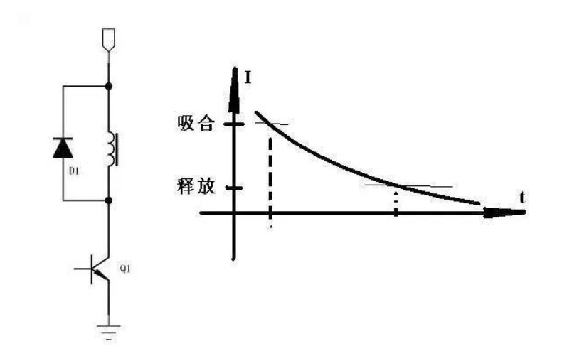
In the figure, the coil of the relay passes through Q1 as a switch to turn it on and off. D1 acts as a freewheeling current and consumes the energy in the coil.
0 2 Features of Relays
1. The pull-in current is greater than the release current
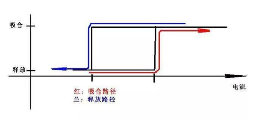
2. The holding current is less than the pull-in current and greater than the release current.
The above two points are the "common problems" of relays. You can do an experiment or take a look at the manual.
0 3 Advantages and disadvantages of popular circuits
As we all know, the coil of a relay is equivalent to an inductance, and its current cannot be abruptly changed. When released, when Q1 is turned off, the coil will still maintain the original current size. If the diode D1 is not connected, the voltage generated is theoretically infinite (when the external circuit load is infinite), in the popular circuit The access of D1 provides a release channel for the energy in the coil.
However, if (theoretically) the diode is ideal, i.e. it conducts only one way and does not dissipate any power, then when the relay is released, the current in the coil will always remain at the maximum current that was picked up (and assuming the coil is ideal ), which will prevent the relay from releasing.
The actual diode and coil are not ideal, so it can be released. The pull-in to release of the relay is determined by the current in the coil. If the equivalent resistance (DC) of the diode and the coil is small, its release time will be very long, otherwise, it will be shorter.
From this point of view, the advantage of the popular circuit is that it provides an energy release channel when Q1 is turned off; its disadvantage is that the release time may be further shortened.
0 4 relay other connection
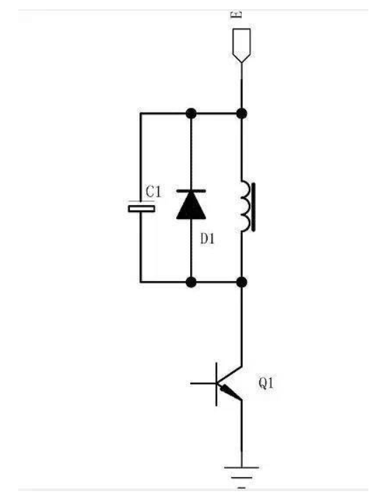
I have seen the circuit as shown in the figure below, and I have seen the connection method without a diode as shown in the figure below. These connection methods have taken into account the reverse voltage when the suppression switch Q1 is turned off, but have not considered the release time issue.
0 5 recommended connection
1. Add resistor R1 to make the energy release faster.
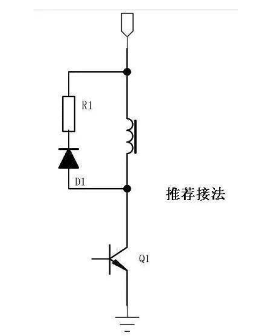
In the above picture, when the coil turns off Q1, the energy is mainly consumed on R1, so that the relay can quickly drop to release current.
The choice of R1 is determined by the highest back pressure of Q1 and the working current of the coil. The greater the resistance, the shorter the release time. ---- Not to mention the calculation.
2. Reduce the power consumption when the relay is held.
As we all know, the relay needs a larger current when it is pulled in, and the current does not need to be the same as when it is pulled in to maintain the pull-in state.
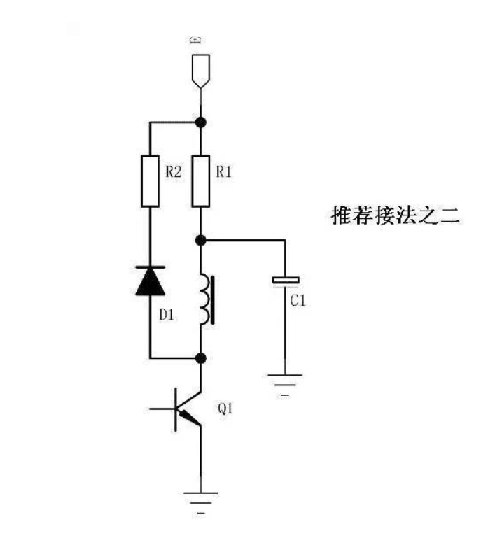
Connecting R1 and C1 in the figure below will significantly reduce the holding power consumption of the relay. Before the relay is pulled in, C1 has been charged to the supply voltage, and the moment of pull-in will be changed from C1 to
The relay is powered to ensure the high current required for pull-in. When pulled in, the current supplied to the coil comes from R1, which limits the current to a smaller state.
